Categories: Beginner
This tutorial will walk you through how to use the
PCB Ruler
to measure things that are longer than the maximum measuring capacity of the ruler (6 in) using
sonar technology
and RGB LEDS.
Step 1: Materials
Below is list of materials used in this project:
Hardware:
RGB LED (4)
Soldering Iron
Wire
Software:
Step 2: Circuit Setup
The
PmodMAXSONAR
is a ultrasonic range finder with effective detection range of ~6 in – 255 in. It’s capable of reading measurements three ways at once – through UART, analog and PWM. In this project I use only the analog feature to record distance measurements.
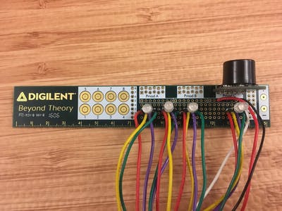
Each RGB LED has four legs, follow the picture above to determine which leg is which, but the idea is one leg controls the red LED, then blue, green, and a fourth leg for PWM control.
Solder the LEDs in place. I put three relatively close to one another and the one I wanted as my 10x multiplier I offset a little bit from the rest. I chose wires that matched the LED color for each diode, and soldered those in place.
Next, solder in the
Pmod
. I used Pmod slot C on the
PCB Ruler
. We only need three pins from the
MAXSONAR
– VCC, GND and AN. It requires 3.3 V power supply. Pin 6 is voltage (VCC), pin 5 is ground (GND), and pin 1 is analog (AN).
Solder in the wires to the
Pmod
and that’s it for the circuit. I cut the wires all to the same length (about an arms length) – because they’ll be plugged into the
BeagleBone Black
, longer wires will prevent any annoying or harmful tug while using the ruler.
I used two ~3 inch long pieces of heat shrink to keep everything neat. One piece towards the ruler and one towards the other end of the wires.
Step 3: Software Setup
Using
LabVIEW 2014
and
LINX 3.0
, I can target the
BeagleBone
Black. If you’re unfamiliar with
LINX 3.0
or need help doing the firmware installation on your
BeagleBone
,
these tutorial videos
walk you through the entire process.
Although the
PmodMAXSONAR
has its own set of VI’s through
LINX 3.0
, we won’t use them this time. All we have to do is read from the analog output on the
Pmod
.
Each diode on the RGB LEDs requires its own digital output. The PWM control for each LED also requires its own PMW channel coming from the
BeagleBone
. I have the channels set as constant in the block diagram, but you can change those if you decide to switch the LED digital or PWM channels.
For every inch the
MAXSONAR
sees past 6, it will light up the first diode in the first LED (red), then the second diode in the first LED (green) for the next inch, etc. This will cycle through for however far the object you’re trying to measure is. Once all three LEDs cycle through the fourth LED will illuminate red – this LED acts as a 10x multiplier for each of the subsequent LED colors.
Step 4: Thank You!
Thank you for viewing my tutorial and please feel free to comment below or message me with any questions.


Comments are not currently available for this post.