Categories: Intermediate
Motivation
In the technological age, it is easy to forget the value of the visual and auditory arts that are not used solely for commercial purposes. Yet this same age also offers us new tools that we can use to appreciate these more abstract forms of the representation of human wit. This project sets out to do just that: to use the tools at our advantage to interpret colors with sounds.
Overview
This project should work by spinning a hardboard wheel with different colors pasted to it. As it slowly spins, a color sensor mounted above the box will read the color. The Pocket Beagle then uses that color to output a tone and change the color of a common-anode RGB LED.
User
Information
To fully enjoy your "Colorful Tunes" design, first cut out a 5 in. cardboard circle. You won’t want to use anything heavier than cardboard because of the increased moment of inertia that would bring. This would then result in a rotor that is difficult to control, so stick with cardboard or any light material. Though I used a laser cutter which took in an AI file, feel free to use a compass and a pair of scissors! The important thing is getting the circle. The one I made with the laser cutter is seen in figure 1.
If you use a laser cutter to make your circle, be sure to put a small circle just slightly smaller than the shaft of your motor. This will ensure that there is a friction connection between the two. Mine did not come out too tight, so I had to apply a dollop of hot glue on the hole to make sure the shaft stays in place. I also placed a piece of tape on the back so that the wheel does not move into the motor shaft. Refer to figure 2 for my motor/cardboard wheel combination.
Next of importance is the color wheel itself. The color sensor used in this project tells things as it sees them, and it can sometimes be quite blind. To ensure that your sensor is reading the right color, use white card stock paper. Figure out how many musical notes you are going to represent, assign them a color, and then divide your board accordingly! You may find that the sensor is limited to under 10 notes, unless you get a larger circle. This larger circle. Then, use a pair of scissors to cut out a slot along one of the radii, and then slide this slot over the motor shaft. Tape down the card stock color wheel to the boring old cardboard wheel. Refer to figure 3 for how mine came out!
Now, apply a Velcro picture command strip to the flat end of the DC motor. The other pair should be attached to the box. See figure 4 for what I mean! You can use the Velcro to adjust your motor and the distance the wheel is from the sensor as necessary.
Congratulations! You are ready to read colors. Turn on the pocket beagle (which is currently on a breadboard, unless you find a way to integrate it with the box, which should be a fun exercise in spatial organization), and with the aid of the shell script, the program should automatically boot. Play around with the knob settings a little bit to find the ideal speed. It should be rather low.
Future iterations of this project will actually have music! What you will do in this case is simply connect the speaker of your choice to the plugable USB Audio Adapter, and listen to the tunes your pocket beagle has created for you.
The Electronics
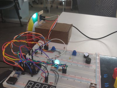
To get this project fully operational, refer to the table with the bill of materials. The most important components, besides your beagle board, are your plugable USB Audio Adapter combined with the USB Micro-B Breakout Board, the RGB LED (My code assumes the use of a common anode RGB LED, but you can choose whichever one you want, just tweak the PWM outputs), the DC Motor (anything rated for 5V and under should be perfect), and the Color Sensor with an IR filter. Refer to figure 5 for the Fritzing diagram, and if you want to modify any components on the breadboard, feel free to install the Fritzing file.
In case you need to modify anything, however, refer to the following general table of which part belongs where:
Color Sensor –> I2C Bus
Ensure there is a voltage lift between SCL and SDA pins. Hook up a 2.2 KOhm resistor from each of these to a 3V3 power source.
Color sensor requires anywhere between 3 volts and 5 volts to light up the LED.
Motor –> 5V power, Ground
This motor is a bit tricky to visualize. First connect one of the motor leads to any 5V terminal on the Pocket Beagle, but connect one of the leads to a 902N3904L transistor source pin. Connect the gate pin of this transistor to a PWM pin from the Pocket Beagle. Then connect the sink to ground.
Potentiometer –> AIN 1V8
Plug in P1_18 to one of the external pins on the potentiometer and P1_17 to the other. Plug the middle pin into any of the AI pins.
RGB LED:
Connect the long pin to a constant 3V3 output from the pocket beagle. Hook up each leg to a resistor and then to a PWM pin each. It is very important that you use a PWM!
Hex Display:
Do the same thing as with the color sensor, as this Hex display works like an I2C bus. Only, do not use the same I2C bus as the Color Sensor, or you will confuse your pocket beagle.
USB Micro-B Breakout Board:
This one requires you to prep your beagle. Do a solder bridge between P1_5 and P1_7. Then do another solder bridge between P1_13 and P1_15. So that you don’t have to look for the pin orientation online outside of this warm, safe website, refer to figure 6 for the pins on the pocket beagle.
The
Box
This box can be done with a laser cutter and without one, it is totally your choice! If you want to be accurate and use a laser cutter,
makeabox.io
is a great tool! If you want to just cut it with a jigsaw, use a hardboard 1/8" plank. It does not matter how you cut your piece, as long as the final box is 4-1/4" by 1-1/2" by 2-5/8". Make sure you select the option for open ended! Also, make sure you have a middle plank for the motor to attach to.
With future iterations, once the pocket beagle can be removed from the breadboard and placed onto the box, these numbers might change. And as you find any possible changes, feel free to adjust these dimensions!
How
it works
Refer to the attached video! Basically, you run the program "Colorful_Tunes_Real2.py" and then adjust the motor speeds with the blue potentiometer. I accidentally refered to it as an engine in the video, but no, it is not an engine.
There is some significant lag, but that can be changed by setting a different update time or by getting a quicker sensor. Furthermore, the whole process could be streamlined by replacing the simple DC motor with a 360 degree servo motor. This one would ensure that the speed is more controlled, and you could even play around with the settings on the potentiometer to turn the servo! Become a colorful DJ with every session.
Future Improvements
If you have gone through the code, you will see that not everything is represented. For starters, I do not output audio just yet, nor do I use my hex display. The former reason is due to not discovering the wonders of SoX audio on time. You can use this by doing the following command.
sudo apt-get install sox
Then, play around with it! A teacher from a Montessori School has this very useful webpage:
http://montessorimuddle.org/2012/04/19/generating-and-saving-tones-with-sox/
These commands work perfectly! Using the PWM values Nicholas Lester found, you can even play songs! The color wheel I am using is meant to eventually play the first line from the famous song "Oh Susanna." Red corresponds to the musical note "C, " yellow to "D, " Green to "E, " Blue to "G, " and Orange to "A." I find that the notes from C4 to B4 on Nick’s Hackster page are more pleasing to the ear.
Here is Nick’s page:
https://www.hackster.io/nickericlester/ir-breakbeam-candy-dispenser-with-zelda-music-c76e65#toc-useful-links-7
His project is also super cool, so check it out!
Another thing you could do is reconcile the libraries used by the color sensor and the hex display. The hex display uses a good old BBIO library, which was improved by Erick Welsh, but the color sensor uses a circuitPython library. This requires you to install blinka and board, but it really does not like sharing with BBIO. Therefore, your challenge, in order to properly get the LED to work, is to use a circuitPython library on the hex display. Or maybe I’ll do it. In which case, I’ll just update this page.
Cool
Links
Color Sensor Resources:
https://learn.adafruit.com/adafruit-color-sensors/overview
Using BBIO (Not too helpful but good for fiddling around):
https://learn.adafruit.com/setting-up-io-python-library-on-beaglebone-black/using-the-bbio-library
Using Circuit Python:
https://learn.adafruit.com/circuitpython-on-raspberrypi-linux/installing-circuitpython-on-raspberry-pi
Good Explanation on RGB LEDs:
https://learn.adafruit.com/adafruit-arduino-lesson-3-rgb-leds/theory-pwm
Remember the two libraries are at war with each other! Will you be able to make the peace?
Please please please install SoX! Do NOT be like me trying to figure out Aplay to generate tones, it won’t work.
Comments are not currently available for this post.